Article -> Article Details
| Title | How to Install a Rear Mount Rack in a GE Fanuc Control System |
|---|---|
| Category | Business --> Consumer Goods and Services |
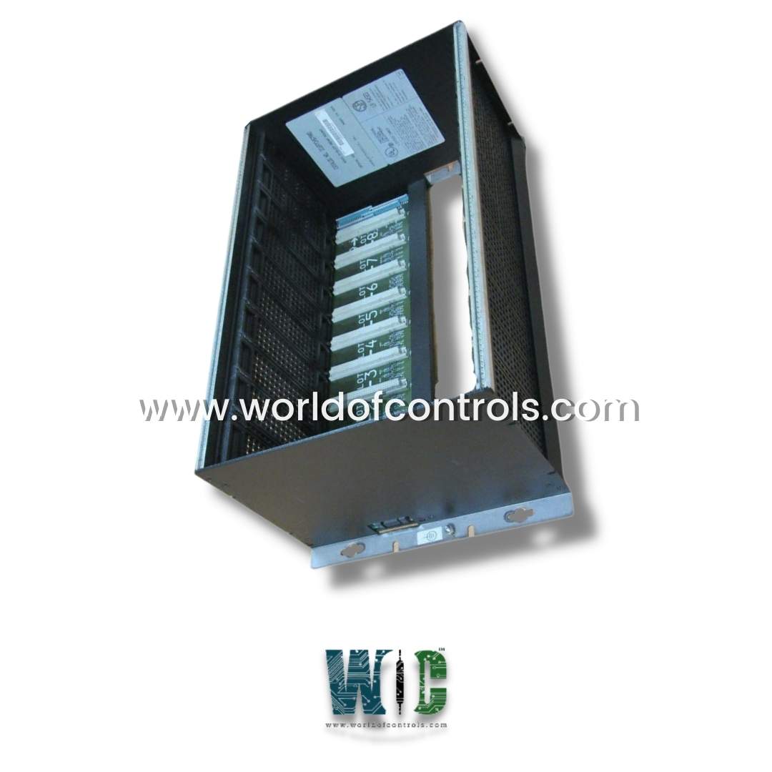
| Meta Keywords | IC697CHS790 |
| Owner | World Of Controls |
| Description | |
| In mission-critical industries like power generation, particularly in turbine operations, the reliability of control systems is non-negotiable. One essential component that ensures stability and scalability is the proper installation of a rear mount rack in a PLC setup. This guide walks you through the installation process of a rear-mounted rack in a GE Fanuc Series 90-70 control system, with a special focus on its importance in turbine environments.
The Role of Rear Mount Racks in PLC Systems Rear mount racks are designed for secure, space-saving installation inside control cabinets. They are especially beneficial in turbine control systems where panel space is limited, and environmental conditions can be harsh. By mounting directly to the rear panel, these racks offer clean wiring paths, improved airflow, and robust support for multiple modules. Relevance to the Turbine Industry Turbine operations demand continuous monitoring, real-time control, and quick diagnostics. Rear mount racks in GE Fanuc PLC systems help meet these needs by providing a reliable physical platform for CPUs, power supplies, communication modules, and I/O interfaces. Their compact and sturdy design makes them well-suited for the vibration and heat-prone environments common in turbine generator rooms. Pre-Installation Checklist Before installing your rear mount rack, go through this checklist to ensure safety and compatibility:
Step-by-Step Installation Guide 1. Mounting the Rack Choose a mounting location on the rear panel of your control cabinet. Mark the mounting holes based on the rack’s dimensions and use proper fasteners to securely attach it. Stability is crucial to withstand vibrations common in turbine setups. 2. Installing Modules Begin by installing the power supply module, usually on the far left slot. Follow with the CPU and then any I/O or communication modules. Make sure each module is firmly seated in the rack and properly aligned with the internal backplane. 3. Backplane Connection Rear mount racks include an integrated backplane that connects all installed modules. Double-check that every module is making proper contact to ensure reliable data and power transfer. 4. Cabling and Grounding Organize wiring neatly to prevent interference and overheating. Use proper grounding techniques to eliminate electrical noise—a critical factor for accuracy in turbine control systems. Testing and Commissioning After installation:
Conclusion Rear mount racks are a cornerstone of stable and scalable PLC systems in the turbine industry. Proper installation within a GE Fanuc control system ensures reliability, enhances control accuracy, and supports long-term system performance. By following these steps, you’ll be well on your way to building a control system capable of handling the demands of modern turbine applications. To avail our best deals for 246B8279G1 and 267B6293P0010, contact us and we will get back to you within 24 hours. | |